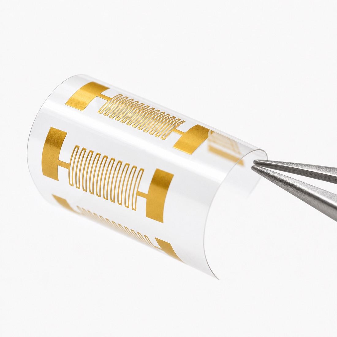
In high-frequency electronics, electromagnetic interference (EMI) can degrade signal integrity, cause regulatory non-compliance, and lead to costly redesigns. Copper foil remains the preferred material for EMI shielding due to its high conductivity (≥58 MS/m), ease of fabrication, and compatibility with flexible and rigid assemblies. However, selecting the correct copper foil thickness and specifying precise cutting methods—particularly laser cut copper foil—directly impacts shielding effectiveness, mechanical fit, and manufacturing cost. This guide provides procurement engineers and design teams with the technical parameters needed to specify copper foil for EMI shielding applications, covering material options, thickness selection, cutting tolerances, and documentation requirements.
Quick Answer
For most EMI shielding applications, specify annealed (soft) copper foil in thicknesses from 0.018 mm (0.7 mil) to 0.10 mm (4 mil). Use 0.035 mm (1 oz/ft²) for general-purpose gaskets and enclosures; 0.05–0.07 mm for flexible circuits and cable wraps; and 0.10 mm or thicker for structural shielding requiring mechanical rigidity. Laser cutting is the preferred method for achieving burr-free edges, tight tolerances (±0.05 mm), and complex geometries without introducing mechanical stress. Always request material certificates and surface finish specifications to ensure adhesion for conductive adhesives or soldering. For a full overview of available alloys and tempers, consult the copper foil material selection page.
Material or Process Considerations
Copper foil for EMI shielding is typically produced in two forms: electrodeposited (ED) and wrought (rolled annealed). ED foil offers a matte side suitable for bonding to substrates, while rolled foil provides superior ductility and a smoother surface for high-frequency applications. The choice between them depends on the shielding frequency range and mechanical requirements. Below are key material and process factors:
- Thickness vs. shielding effectiveness: At frequencies above 1 MHz, a 0.035 mm copper foil provides >60 dB attenuation; increasing thickness to 0.10 mm improves low-frequency (below 100 kHz) magnetic field shielding by reducing skin-depth limitations.
- Surface finish: For adhesive-backed shielding, specify a bright or treated surface (e.g., zinc or nickel flash) to improve corrosion resistance and bond strength. Bare copper requires controlled humidity storage to prevent oxidation.
- Cutting method: Laser cutting eliminates tooling wear and produces clean edges without delamination. Mechanical die cutting is cost-effective for simple shapes at high volumes but may leave micro-burrs that compromise thin-gap assemblies. Laser cutting services can achieve repeatable tolerances of ±0.03 mm on parts up to 300 mm in size.
- Bonding and lamination: If the foil will be bonded to a dielectric substrate (e.g., polyimide or PET), specify rolled annealed foil with a surface roughness (Ra) below 0.3 µm to ensure uniform adhesive coverage.
How to Select the Right Option
Selecting the optimal copper foil thickness and cutting process requires balancing electrical performance, mechanical constraints, and cost. Follow these steps to define your specification:
Step 1 – Determine the required shielding effectiveness (SE). For electric field shielding at frequencies above 1 MHz, a 0.035 mm foil typically provides 60–80 dB attenuation. For magnetic field shielding below 100 kHz, thicker foils (0.10–0.20 mm) are necessary to achieve 30–40 dB. Use the formula SE (dB) ≈ 20 log(1 + σ·t·f / 2) for initial estimation, where σ is conductivity in S/m, t is thickness in meters, and f is frequency in Hz.
Step 2 – Evaluate mechanical requirements. If the foil must conform to curved surfaces or undergo repeated flexing (e.g., cable wraps or gaskets), choose rolled annealed foil with 0.05–0.07 mm thickness. For rigid enclosures or grounding planes, 0.10–0.20 mm ED foil provides sufficient stiffness.
Step 3 – Assess production volume and geometry complexity. For prototypes and low-volume runs (up to 500 pieces), laser cutting is the most flexible and cost-effective method, as it requires no hard tooling. For high-volume runs (>10,000 pieces) with simple shapes, mechanical stamping or rotary die cutting can lower per-part cost. Submit a custom quote with your 2D drawing and quantity to compare pricing.
Step 4 – Specify tolerances and edge quality. For applications where the foil fits into narrow slots or around connectors, request laser-cut edges with a maximum burr height of 0.02 mm. For general-purpose gaskets, ±0.10 mm tolerance is acceptable.
Buyer Checklist
- Material grade and thickness: Specify C11000 or C10200 copper; state nominal thickness and tolerance (e.g., 0.035 mm ±0.005 mm).
- Drawing format and tolerance: Provide 2D CAD (DXF or DWG) with overall dimensions, hole locations, and edge finish requirements.
- Required documents: Request mill test certificates (MTC) per ASTM B152/B152M, surface roughness report, and RoHS/REACH compliance statements.
- Quantity and packaging: Define per-lot quantity, acceptable splice count (for rolled foil), and packaging method (interleaved paper, anti-tarnish wrap, or vacuum sealing).
Documents and RFQ Notes
When requesting a quotation for custom copper foil parts, include the following in your RFQ: a clear indication of whether the application requires ED or rolled foil; the target shielding frequency range; and any post-processing needs such as adhesive lamination, hole drilling, or surface treatment. For complex parts with internal cutouts or micro-patterns, specify the minimum feature size and whether micro-hole drilling is required for ventilation or cable pass-throughs. If the foil will be integrated into a flexible assembly, note the bend radius and cycle life expectations. For applications requiring extreme precision, such as aerospace or medical devices, reference femtosecond laser micromachining for heat-affected-zone-free cutting. Always attach a dimensioned drawing in PDF and editable format, and indicate the acceptance criteria for edge burrs and surface contamination.
Common Mistakes to Avoid
- Over-specifying thickness: Using 0.10 mm foil when 0.035 mm would suffice adds unnecessary weight and cost, and may cause fitting issues in tight enclosures. Always verify skin depth at the lowest operating frequency.
- Ignoring surface treatment: Bare copper foil oxidizes rapidly in ambient conditions, reducing solderability and adhesive bond strength. Specify a protective coating (e.g., clear acrylic or nickel flash) unless the foil will be encapsulated immediately.
- Assuming all laser cutting is equivalent: Standard laser cutting may produce a heat-affected zone (HAZ) on thin foils, causing edge discoloration or embrittlement. For foils below 0.05 mm, request femtosecond laser cutting to eliminate thermal damage.
- Neglecting tolerances for adhesive layers: If the foil is supplied with a conductive adhesive backing, the total thickness tolerance must account for the adhesive layer (typically ±0.015 mm). Specify the combined thickness in your drawing.
FAQ
What is the minimum thickness of copper foil for effective EMI shielding at 1 GHz?
At 1 GHz, the skin depth of copper is approximately 2.1 µm. A foil thickness of 0.018 mm (18 µm) provides over 8 skin depths, yielding >60 dB shielding effectiveness. For most applications, 0.035 mm is recommended as a safe margin.
Can laser-cut copper foil be used for flexible circuits?
Yes, but only if the foil is rolled annealed (wrought) and the laser parameters are optimized to minimize HAZ. Femtosecond laser cutting is preferred for flexible circuits because it produces no thermal distortion, preserving ductility. See application examples for flexible circuits.
How do I specify tolerance for a laser-cut copper foil gasket?
For a standard gasket, specify ±0.10 mm on overall dimensions and ±0.05 mm on hole positions. For critical sealing surfaces, request ±0.03 mm. Always include a note that edge burrs must not exceed 0.02 mm.