Battery metal foil tabs, current collector prototypes and connector plates look simple on a drawing, yet they sit at the intersection of electrical, thermal, mechanical and electrochemical requirements. A useful sourcing package must define more than an outline and thickness: it should explain the component’s role, material condition, joining interface, cleanliness, inspection and responsibility for cell-level validation.
Quick answer
A battery metal foil tab, current collector prototype or connector-plate RFQ should define the cell or test-fixture function, base material, grade or purity, thickness, temper, surface condition, geometry, joining method, quantity, cleanliness, inspection and traceability. The correct material cannot be selected from conductivity alone because electrochemical compatibility, joining, mechanical strength, corrosion, heat flow and the complete cell design also matter.
Finalfoil supplies ultra-thin copper, nickel, stainless steel and specialty metal foils and reviews custom tabs, slots, windows, perforated grids and retained-frame prototypes for femtosecond, picosecond or other precision laser processing. Feasibility is evaluated from the current drawing, material, thickness and acceptance method rather than a universal feature or tolerance claim.
Current collector, tab, connector plate and busbar are different parts
A current collector supports the electrode system and carries current from the active region. A tab connects that collector to a terminal or another conductor. A connector plate may link cells, test coupons or sensing points, while a busbar distributes higher current at module or pack level. A perforated foil or grid can be used for experimental coating, electrolyte access, weight reduction, sensing or specialized cell architectures.
These names should not be used interchangeably in an RFQ. A thin current collector may prioritize surface, coating adhesion and uniformity. A tab may be governed by weld area, bend behavior and heat flow. A connector plate may require mechanical stiffness and positional accuracy. State what the component does and where it sits in the assembly before discussing the cutting process.
Compare foil materials around the cell design
| Material option | Why engineers consider it | What the RFQ must confirm |
|---|---|---|
| Copper foil | High electrical and thermal conductivity with broad current-collector and connector use | Purity or alloy, temper, surface, coating process, oxidation control and joining route |
| Aluminum foil | Low mass and established use in selected current-collector and tab systems | Alloy, temper, surface treatment, electrochemical compatibility and welding method |
| Nickel foil | Selected for tab, connector, temperature, corrosion or joining requirements | Exact grade, conductivity, hardness, weldability, plating and service environment |
| Stainless steel foil | Mechanical stability and corrosion resistance for fixtures, spacers and research components | Grade, temper, electrical role, passivation, joining and whether direct cell exposure is intended |
| Plated or layered material | Surface and joining behavior can be tailored for a specific interface | Base metal, coating stack, finished thickness, exposed edges and dimensional stage |
Common lithium-ion manufacturing uses copper and aluminum foils in different electrode roles, but the device owner must select materials for the actual chemistry and voltage window. Nickel, stainless steel and plated systems may serve tabs, connectors, test hardware or specialized cells rather than replacing the main current collector automatically. Research projects should identify whether the requested part is electrochemically active, electrolyte-exposed or outside the sealed cell.
Review available materials in the metal foil materials database, including copper foil, nickel foil and 304 stainless steel foil. For battery-focused project context, also review battery and energy metal foil applications.
Thickness affects more than electrical resistance
Foil thickness changes electrical cross-section, thermal path, stiffness, handling and the energy needed for joining. Reducing thickness may save mass or volume, but it can also increase wrinkling, tearing and sensitivity to coating or assembly stress. A thicker tab can carry load differently and may require a different weld schedule or transition geometry.
Specify nominal thickness, variation and the measurement method. If plating, coating, lamination or surface treatment changes the finished section, state whether dimensions apply to the incoming foil or completed component. For layered parts, list the thickness and material of every layer instead of giving only a total stack value.
Temper and surface condition must match downstream operations
Soft foil may conform and form easily but can be vulnerable during handling. Harder conditions may improve shape retention while changing bend behavior and weld response. Rolling direction can matter when tabs are bent, narrow bridges carry load or a perforated grid must remain flat.
Surface condition influences coating, bonding, welding and electrical contact. Define whether the foil is bare, plated, treated, cleaned or intentionally roughened. Do not use generic words such as battery grade without a material designation and measurable surface requirement. If the supplier is allowed to propose an equivalent, list the properties and validation steps that control approval.
Design the tab-to-foil joining region before cutting the outline
A tab drawing should show the joining zone, terminal end, bend lines, locating features and keep-out areas. The joint may use laser welding, ultrasonic welding, resistance welding, soldering, brazing, mechanical clamping or another qualified process. Each route has different requirements for material pairing, surface condition, overlap, thickness and heat input.
Dissimilar-metal joints require special attention because electrical, thermal and metallurgical behavior can change at the interface. Finalfoil can manufacture a flat foil component, but the joining process and cell safety must be developed and validated by the responsible device team. Send representative mating materials with the RFQ when process trials are part of the project.
Use perforated collectors and grids only for a defined function
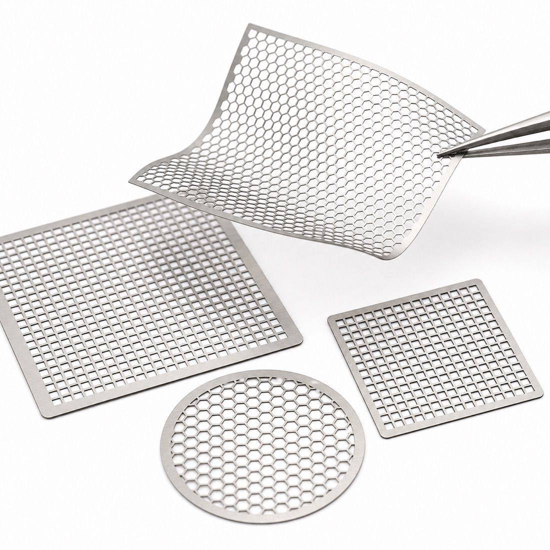
Perforations can change mass, open area, coating retention, electrolyte access, flexibility and current distribution. The pattern should be tied to a test hypothesis or device requirement rather than added as visual decoration. Define aperture shape, pitch, open-area target, border width, current path and the position of solid joining zones.
A high open area can reduce available conductive cross-section and mechanical support. Narrow ligaments can be sensitive to handling, coating and release from a carrier. The device owner should model and test electrical, thermal and mechanical behavior. The supplier should confirm whether the requested pattern can be cut, cleaned, inspected and shipped without unacceptable damage.
When precision laser cutting may support battery development
Laser processing can support prototype tabs, shaped current collectors, sensor openings, slots, perforated grids and frequent design revisions without dedicated hard tooling. Femtosecond processing may be reviewed where fine geometry or thermal influence near a thin foil feature is important. Picosecond or conventional precision laser cutting may be more efficient for other materials and feature scales.
Reflectivity, thickness, pattern density, heat flow, debris control, fixturing and inspection method still influence feasibility. Ultrashort pulses do not remove every edge, oxide, discoloration, recast or distortion concern. Finalfoil reviews these factors through its femtosecond laser micromachining service before confirming a process route.
Separate cut-part cleanliness from cell-level cleanliness
Battery components can be sensitive to particles, oils, fibers, moisture and residues, but required controls vary widely between open laboratory fixtures and sealed production cells. The RFQ should identify prohibited materials, cleaning agents, drying condition, packaging environment and whether the component will enter a dry-room or glovebox process.
The foil processor should not claim that a part is ready for every battery assembly based only on visual cleanliness. The cell manufacturer remains responsible for incoming controls, final cleaning, drying, contamination limits and process validation. If analytical testing is required, define the method, sampling and acceptance level before quotation.
Carrier frames can protect thin tabs and grids
Loose thin parts can wrinkle, tangle or lose orientation. A surrounding frame or indexed strip may support cutting, inspection, cleaning and automated transfer. Temporary tabs should remain outside weld zones, coated areas, sealing lands and active current paths.
- Mark the active part and temporary carrier geometry separately.
- Identify which face contacts coating, electrolyte, terminal or fixture.
- Show grain-direction and bend-orientation requirements.
- Define allowed tab witnesses after release.
- State whether parts ship loose, nested, reeled, framed or individually packed.
- Keep material lot and drawing revision with every package.
Build inspection around the component function
Dimensional inspection may include profile, aperture size, slot width, pitch, border width, tab width, hole position, thickness, flatness and visible edge condition. Optical measurement on reflective thin foil depends on lighting, focus, threshold and part support, so critical features need an agreed measurement rule.
Electrical resistance, current capacity, weld strength, fatigue, temperature rise, electrochemical stability and abuse behavior require separate testing on representative joints or complete cells. A dimensional report cannot replace cell qualification. Define which records come from the foil supplier and which belong to the battery developer or approved test laboratory.
Supplier evaluation checklist
- Does the supplier distinguish collectors, tabs, connector plates and busbars?
- Can material, thickness, temper, surface and joining be reviewed together?
- Are electrolyte exposure and electrochemical compatibility assigned to the device owner?
- Will the supplier review carriers, tab witnesses, cleaning and packaging?
- Are dimensional inspection and battery performance validation clearly separated?
- Can available MTC, CoA, SDS, TDS, RoHS or REACH records be confirmed early?
- Can prototypes remain traceable through material lot, drawing number and revision?
RFQ information to send
- Cell, module, laboratory or fixture application
- Function of the collector, tab, connector plate or perforated grid
- Material grade or purity, thickness, temper and surface condition
- DXF or DWG geometry plus a dimensioned PDF
- Current path, joining zone, bend lines, coating area and keep-out zones
- Cleaning, drying, carrier and packaging requirements
- Prototype quantity, expected production quantity and revision status
- Dimensional, joining, electrical and material-document responsibilities
Frequently asked questions
Is nickel foil the standard current collector for every battery?
No. Material selection depends on chemistry, voltage, architecture and joining. Nickel may serve tabs or connectors in selected designs, while other foils serve different current-collector roles.
Can Finalfoil guarantee battery performance from a tab drawing?
No. Finalfoil can review material supply, laser processing and dimensional inspection. Cell safety and performance require qualified joining, assembly and testing by the responsible device team.
What is the smallest grid opening Finalfoil can process?
There is no universal value for every material and inspection method. Send the foil, thickness, pattern, quantity and acceptance plan for current feasibility review.
Request an engineering review
Send the battery or research application, component function, material, thickness, flat drawing, joining interface, cleanliness requirement, prototype quantity and inspection plan. Finalfoil will review foil supply and the current processing route before quotation.